|
 |
|
|
|
|
|
 |
|
|
|
|
|
|
|
|
|
|

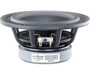
- Balanced Drive motor structure for optimal drive force symmetry resulting in largely reduced even order harmonic distortion
- Copper cap on center pole to reduce voice coil inductance and to minimize variations in voice coil inductance as a function of voice coil position
- Cone made of a new paper/glass fiber mix with improved consistency and stability
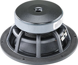
- Rigid die cast alu chassis with extensive venting for lower air flow speed reducing audible distortion
- Vented voice coil former for reduced distortion and compression
- Vented center pole with dual flares for reduced noise level at large cone excursions
- Heavy-duty black fiber glass voice coil former to reduce mechanical losses resulting in better dynamic performance and low-level details
- Large motor with 39 mm voice coil diameter for better control and power handling
- Built-in alu field-stabilizing ring for reduced distortion at high levels
- Low-loss suspension (high Qm) for better reproduction of details and dynamics
- Black motor parts for better heat transfer to the surrounding air
- Conex spider for better durability under extreme conditions
- Gold plated terminals to ensure long-term trouble free connection
|
|
|
|
FREQUENCY RESPONSE
|
|
|
|
|
|
|
|
|
Downloads
SPL and impedance response curves as text files
|
|
|

|
WF182BD17/19 SPL response
|
|
WF182BD17/19 impedance response
|
|
|
WF182BD18/20 SPL response
|
|
WF182BD18/20 impedance response
|
|
|
|
|
Important!
Please observe that these text files for download are actual measurements of the drivers measured in infinite baffle and without any enclosure. Measuring the drivers in a finite baffle (like the baffle of most speaker cabinets) and in any size of enclosure will lead to different response curves.
|
|
|
|
|
NOMINAL SPECIFICATIONS
|
|
|
|
|
|
Notes
|
Parameter
|
WF182BD17 and WF182BD19
|
WF182BD18 and WF182BD20
|
Unit
|
|
Before burn-in
|
After burn-in
|
Before burn-in
|
After burn-in
|
|
|
Nominal size
|
7
|
7
|
[inch.]
|
|
|
Nominal impedance
|
4
|
8
|
[ohm]
|
|
|
Recommended max. upper frequency limit
|
2.5
|
2.5
|
[kHz]
|
|
1, 4
|
Sensitivity, 2.83V/1m (average SPL in range 200 - 1,000 Hz)
|
88.5
|
86
|
[dB]
|
|
2, 4
|
Power handling, short term, IEC 268-5, no additional filtering
|
400
|
400
|
[W]
|
|
2, 4
|
Power handling, long term, IEC 268-5, no additional filtering
|
250
|
250
|
[W]
|
|
2
|
Power handling, continuous, IEC 268-5, no additional filtering
|
80
|
80
|
[W]
|
|
|
Effective radiating area, Sd
|
131
|
131
|
[sq.cm]
|
|
3, 4, 6
|
Resonance frequency (free air, no baffle), Fs
|
33
|
28.5
|
34
|
29.5
|
[Hz]
|
|
|
Moving mass, incl. air (free air, no baffle), Mms
|
23.4
|
21.9
|
[g]
|
|
3, 4
|
Force factor, Bxl
|
6.5
|
8.2
|
[N/A]
|
|
3, 4, 6
|
Suspension compliance, Cms
|
1.0
|
1.33
|
1.0
|
1.33
|
[mm/N]
|
|
3, 4, 6
|
Equivalent air volume, Vas
|
24.3
|
32.4
|
24.3
|
32.4
|
[lit.]
|
|
3, 4, 6
|
Mechanical resistance, Rms
|
0.44
|
0.46
|
0.44
|
0.46
|
[Ns/m]
|
|
3, 4, 6
|
Mechanical Q, Qms
|
10.9
|
9.1
|
10.5
|
8.8
|
[-]
|
|
3, 4, 6
|
Electrical Q, Qes
|
0.37
|
0.32
|
0.44
|
0.38
|
[-]
|
|
3, 4, 6
|
Total Q, Qts
|
0.35
|
0.31
|
0.42
|
0.37
|
[-]
|
|
4
|
Voice coil resistance, RDC
|
3.2
|
6.4
|
[ohm]
|
|
5
|
Voice coil inductance, Le (measured at 10 kHz)
|
0.10
|
0.17
|
[mH]
|
|
|
Voice coil inside diameter
|
39
|
39
|
[mm]
|
|
|
Voice coil winding height
|
16
|
16
|
[mm]
|
|
|
Air gap height
|
5
|
5
|
[mm]
|
|
|
Theoretical linear motor stroke, Xmax
|
+/-5.5
|
+/-5.5
|
[mm]
|
|
|
Magnet weight
|
725
|
725
|
[g]
|
|
|
Total unit net weight excl. packaging
|
1.95
|
1.95
|
[kg]
|
|
3, 4, 5
|
Krm
|
131
|
117
|
[mohm]
|
|
3, 4, 5
|
Erm
|
0.30
|
0.34
|
[-]
|
|
3, 4, 5
|
Kxm
|
17.5
|
37
|
[mH]
|
|
3, 4, 5
|
Exm
|
0.47
|
0.43
|
[-]
|
|
|
|
|
|
Note 1
|
Measured in infinite baffle.
|
|
Note 2
|
Tested in free air (no cabinet).
|
|
Note 3
|
Measured using a semi-constant current source, nominal level 2 mA.
|
|
Note 4
|
Measured at 25 deg. C
|
|
Note 5
|
It is generally a rough simplification to assume that loudspeaker transducer voice coils exhibit the characteristics of an inductor. Instead it is a far more accurate approach to use the more advanced model often referred to as the “Wright empirical model”, also used in LEAP-4 as the TSL model (www.linearx.com), involving parameters Krm, Erm, Kxm, and Exm. This more accurate transducer model is described in a technical paper (PDF) here.
|
|
Note 6
|
After burn-in specifications are measured 12 hours after exiting the transducer by a 20 Hz sine wave for 2 hours at level 10/14.1 VRMS (4/8 ohm version). The unit is not burned in before shipping.
|
|
|
|
|
HARMONIC DISTORTION
|
|
|
|
|
Part no. WF182BD17-01
|
4 ohm version, individual packaging (one piece per box)
|
|
Part no. WF182BD17-02
|
4 ohm version, bulk packaging
|
|
Part no. WF182BD18-01
|
8 ohm version, individual packaging (one piece per box)
|
|
Part no. WF182BD18-02
|
8 ohm version, bulk packaging
|
|
Part no. WF182BD19-01
|
4 ohm version, truncated frame, individual packaging (one piece per box)
|
|
Part no. WF182BD19-02
|
4 ohm version, truncated frame, bulk packaging
|
|
Part no. WF182BD20-01
|
8 ohm version, truncated frame, individual packaging (one piece per box)
|
|
Part no. WF182BD20-02
|
8 ohm version, truncated frame, bulk packaging
|
|
|
|
|
Latest update: January 30, 2025
|
|
|
|
|
|
|
|
Specifications are subject to change without any further notice.
Copyright © by Wavecor Ltd., China. All rights reserved.
|
|
|
|
|
|
MORE INFO
|
|
|
|
|
 PDF data sheet PDF data sheet
|
|
|
|
Balanced Drive technical paper
|
|
|
|
|
|
|
|
|
|
|
|
|
|
|
|
|
|
|
|
|
|
|
|
|