|
 |
|
|
|
|
|
 |
|
|
|
|
|
|
|
|
|
|
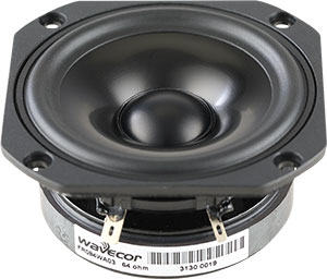
- True full-range design with on-axis output to beyond 20 kHz
- Copper cap on center pole to reduce voice coil inductance and to minimize variations in voice coil inductance as a function of voice coil position
- Black anodized alu cone for better heat transfer
- Vented polymer chassis for lower air flow speed reducing audible distortion
- Vented voice coil former for reduced distortion and compression
- Heavy-duty black fiber glass voice coil bobbin to reduce mechanical losses resulting in better dynamic performance and low-level details
- Large motor with 22 mm voice coil diameter for better control and power handling
- Low-loss suspension (high Qm) for better reproduction of details and dynamics
- Black motor parts for better heat transfer to the surrounding air
- Conex spider for better durability under extreme conditions
- Gold plated terminals to ensure long-term trouble free connection
- Delivered with foam gasket attached for hassle-free mounting and secure cabinet sealing
|
|
|
|
FREQUENCY RESPONSE
|
|
|
|
NOMINAL SPECIFICATIONS
|
|
|
|
|
Notes
|
Parameter
|
FR084WA03
|
Unit
|
|
Before burn-in
|
After burn-in
|
|
|
Nominal size
|
3.25"
|
[inch.]
|
|
|
Nominal impedance
|
64
|
[ohm]
|
|
|
Recommended max. upper frequency limit
|
full range
|
[kHz]
|
|
1, 4
|
Sensitivity, 2.83V/1m (average SPL in range 200 - 8,000 Hz)
|
|
[dB]
|
|
2
|
Power handling, short term, IEC 268-5, no additional filtering
|
30
|
[W]
|
|
2
|
Power handling, long term, IEC 268-5, no additional filtering
|
25
|
[W]
|
|
2
|
Power handling, continuous, IEC 268-5, no additional filtering
|
10
|
[W]
|
|
|
Effective radiating area, Sd
|
36
|
[sq.cm]
|
|
3, 4, 6
|
Resonance frequency (free air, no baffle), Fs
|
|
|
[Hz]
|
|
|
Moving mass, incl. air (free air, no baffle), Mms
|
|
[g]
|
|
3
|
Force factor, Bxl
|
|
[N/A]
|
|
3, 4, 6
|
Suspension compliance, Cms
|
|
|
[mm/N]
|
|
3, 4, 6
|
Equivalent air volume, Vas
|
|
|
[lit.]
|
|
3, 4, 6
|
Mechanical resistance, Rms
|
|
|
[Ns/m]
|
|
3, 4, 6
|
Mechanical Q, Qms
|
|
|
[-]
|
|
3, 4, 6
|
Electrical Q, Qes
|
|
|
[-]
|
|
3, 4, 6
|
Total Q, Qts
|
|
|
[-]
|
|
4
|
Voice coil resistance, RDC
|
|
[ohm]
|
|
5
|
Voice coil inductance, Le (measured at 10 kHz)
|
|
[μH]
|
|
|
Voice coil inside diameter
|
22
|
[mm]
|
|
|
Voice coil winding height
|
|
[mm]
|
|
|
Air gap height
|
3
|
[mm]
|
|
|
Theoretical linear motor stroke, Xmax
|
|
[mm]
|
|
|
Magnet weight
|
160
|
[g]
|
|
|
Total unit net weight excl. packaging
|
0.37
|
[kg]
|
|
3, 4, 5
|
Krm
|
|
[mohm]
|
|
3, 4, 5
|
Erm
|
|
[-]
|
|
3, 4, 5
|
Kxm
|
|
[mH]
|
|
3, 4, 5
|
Exm
|
|
[-]
|
|
|
|
|
|
Note 1
|
Measured in infinite baffle.
|
|
Note 2
|
Tested in free air (no cabinet).
|
|
Note 3
|
Measured using a semi-constant current source, nominal level 2 mA.
|
|
Note 4
|
Measured at 25 deg. C
|
|
Note 5
|
It is generally a rough simplification to assume that loudspeaker transducer voice coils exhibit the characteristics of an inductor. Instead it is a far more accurate approach to use the more advanced model often referred to as the “Wright empirical model”, also used in LEAP-4 as the TSL model (www.linearx.com), involving parameters Krm, Erm, Kxm, and Exm. This more accurate transducer model is described in a technical paper (PDF) here.
|
|
Note 6
|
After-burn-in specifications are measured at least 12 hours after exiting the transducer by a 20 Hz sine wave for 2 hours at level 2.83/4.0 VRMS (4/8 ohm version). Unit are not burned in before shipping.
|
|
|
|
|
HARMONIC DISTORTION
|
|
|
|
OUTLINE DRAWING AND NOMINAL DIMENSIONS (mm)
|
|
|
|
|
|
|
|
Both terminals gold plated
|
|
|
|
|
PACKAGING AND ORDERING INFORMATION
|
|
|
|
|
Part no. FR084WA03-01
|
64 ohm version, individual packaging (one piece per box)
|
|
Part no. FR084WA03-02
|
64 ohm version, bulk packaging
|
|
|
|
|
Latest update: April 17, 2022
|
|
|
|
|
|
|
|
Specifications are subject to change without any further notice.
Copyright © 2006-2021 by Wavecor Ltd., China. All rights reserved.
|
|
|
|
|
|
MORE INFO
|
|
|
|
|
|